Prove your earthing works — digital testers for accurate measurement of earth electrode resistance at commissioning and beyond.
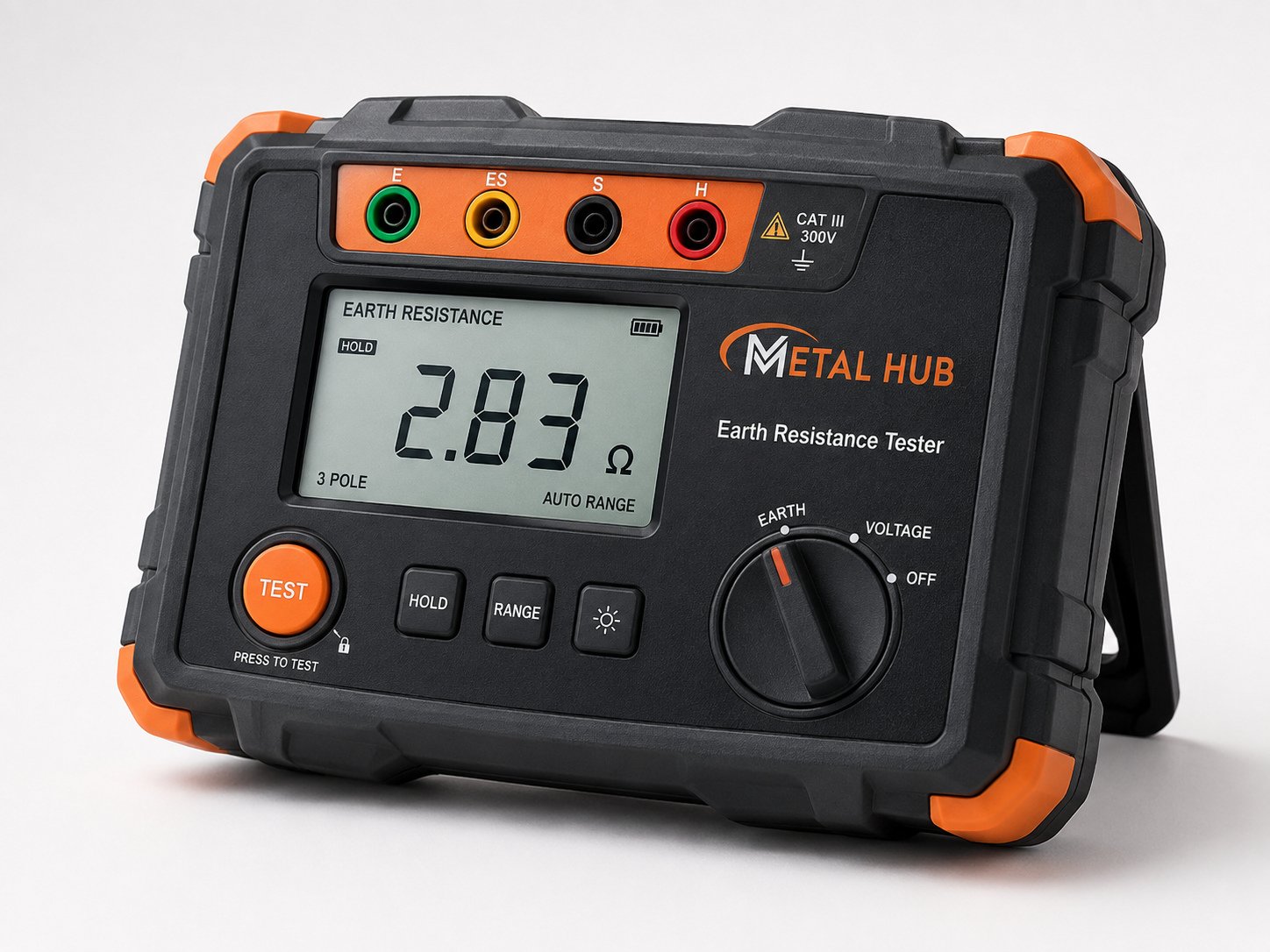
An earthing system is only as good as its measured resistance. Our digital earth resistance testers use the fall-of-potential method to measure electrode and grid resistance accurately, so installations can be certified at commissioning and monitored through their life.
Supplied complete with test leads and auxiliary spikes, the testers are simple enough for routine site checks and accurate enough for compliance records and audits.
| Type | Digital earth resistance tester |
|---|---|
| Method | Fall-of-potential (3-pole) |
| Range | 0 – 2000 Ω (model dependent) |
| Display | Digital LCD |
| Accessories | Test leads and auxiliary earth spikes included |
Every claim made about an earthing system — every electrode, compound bag and strip run — resolves into one number: the measured earth resistance. Codes, insurers and auditors accept nothing else, which makes the tester as fundamental to electrical safety as the electrodes themselves.
The reference method is fall-of-potential: inject a known current between the earth under test and a distant current spike, measure the voltage to a potential spike placed between them, and Ohm's law yields the resistance. Placed correctly — the potential spike at roughly 62% of the distance to the current spike — the method reads the true electrode resistance independent of the instrument operator.
Metal Hub supplies digital three-pole testers with clear LCD readout, complete with leads and auxiliary spikes, ranged 0 – 2000 ohm to cover everything from sub-ohm substation grids to failed pits that need diagnosis. The same instrument doubles for soil resistivity survey work using standard spike geometry.
For organisations that prefer to outsource, our service team performs certified measurements with calibrated instruments — but plants that own a tester test more often, and plants that test more often catch failures before incidents.
Good to know: Always test in the driest month you can: earthing that passes in monsoon and fails in May was never compliant — you just measured it on a good day.
The 62% rule exists because the voltage gradient around an energised electrode flattens in the middle zone between it and the current spike. Placing the potential spike in that flat zone — at 62% of the separation — samples the true resistance; placing it too close reads low, too far reads high. Verifying with readings at ±10% of the position confirms you are on the plateau: three near-identical values mean a valid test.
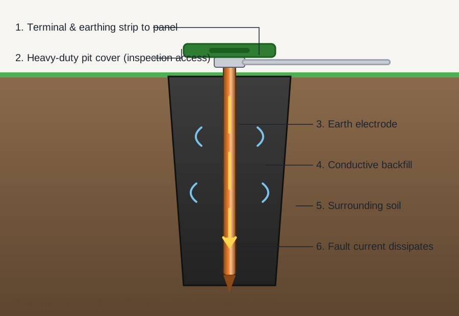
Keep the current spike far enough away — at least five times the electrode depth, commonly 30 – 50 m for standard pits — and disconnect the electrode from the installation via its test link before measuring, so you read the pit alone rather than the whole bonded network in parallel.
| Parameter | Value | Notes |
|---|---|---|
| Method | Fall-of-potential, 3-pole | Reference standard technique |
| Range | 0 – 2000 ohm (auto-ranged) | Sub-ohm grids to failed pits |
| Display | Digital LCD | Unambiguous direct reading |
| Test frequency | Non-power frequency | Rejects 50 Hz interference |
| Accessories | Leads + 2 auxiliary spikes | Complete field kit |
| Also supports | Soil resistivity survey | Standard spike geometry |
Contract specifications prevail; these are the widely used design targets.
| Installation | Typical target |
|---|---|
| Large power station | ≤ 0.5 ohm |
| EHT / major substation | ≤ 1 ohm |
| 33 kV substation | ≤ 2 ohm |
| Industrial plant / DG / transformer | ≤ 5 ohm |
| Commercial building systems | ≤ 5 ohm |
| Residential earthing | ≤ 8 ohm |
| ESE lightning earth termination | ≤ 10 ohm |
| Parameter | 3-pole fall-of-potential | 4-pole | Clamp-on |
|---|---|---|---|
| Accuracy | Reference standard | Highest (removes lead resistance) | Indicative |
| Electrode disconnection needed | Yes (test link) | Yes | No |
| Best use | Routine pit verification | Sub-ohm grids, soil survey | Quick checks on multi-earth networks |
| Open-field spikes needed | Yes | Yes | No |
| Installation | Recommended test interval | Trigger events |
|---|---|---|
| Substations / HT plants | Annual + after modifications | Faults, grid work, excavation nearby |
| Industrial LT systems | Annual (dry season) | Any recorded lightning strike |
| Commercial buildings | Annual | Renovation, added DG or UPS |
| Lightning protection earths | Annual + post-strike | Strike counter increment |
| Residential | Every 2 – 3 years | Any electrical modification |
Open the test link so the pit is measured alone, not in parallel with the building's bonded network.
Drive the current spike 30 – 50 m from the electrode (at least 5× electrode depth) and connect to terminal C.
Drive the potential spike at 62% of that distance on the straight line between them; connect to terminal P.
Connect the electrode to terminal E, inject, and record the displayed resistance once stable.
Repeat with the potential spike moved ±10% of the run; three near-equal readings confirm a valid measurement.
Reconnect the test link, log value, date, weather and instrument ID against the pit number in the earthing register.
The tester itself needs the same discipline it enforces: periodic calibration, healthy leads, and clean spike surfaces. A drifting instrument quietly invalidates an entire year of records.
Store the kit dry, coil the leads without kinks, and verify the instrument against a known resistor before each testing campaign — a thirty-second check that protects the credibility of every number that follows.
Usually the potential spike placement or the season. Apply the 62% rule with the ±10% plateau verification, and always compare readings taken in similar soil moisture — dry-season values are the design-relevant ones.
The current spike should be at least five times the electrode depth away — 30 to 50 m covers standard pits. Cramped tests read artificially low because the voltage gradients of the electrode and spike overlap.
For a true pit measurement, yes — via the test link. Measuring while bonded returns the parallel value of the entire earthing network, which hides an individual failed pit.
Depends on the installation class: ≤ 1 ohm for major substations, ≤ 5 ohm for industrial and commercial systems, ≤ 8 ohm residential, ≤ 10 ohm for lightning terminations — with your contract specification always taking precedence.
Yes — using the standard four-spike survey geometry, the same instrument family produces the soil resistivity data needed to design new earthing before installation.
Annually for commercial and industrial systems (in the dry season), plus after any lightning strike, excavation nearby or electrical modification. Residential systems every two to three years.
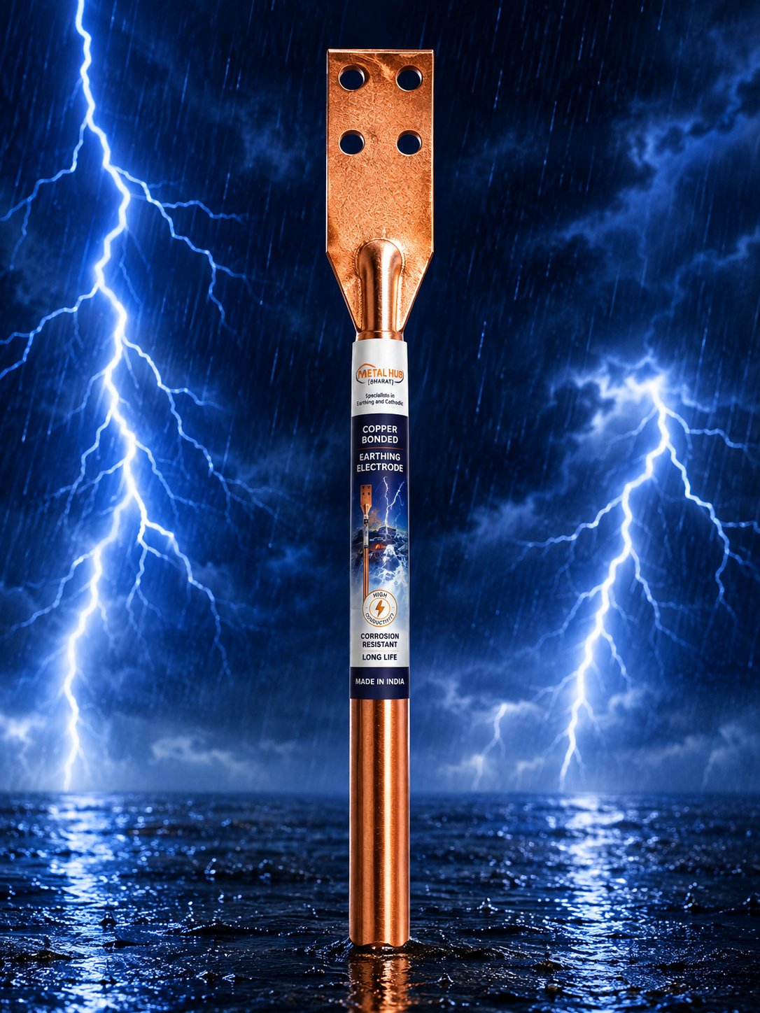
NABL & CPRI lab-tested electrodes with molecularly bonded copper coating.
View Details
Graphite-based ground enhancing compound, resistivity below 0.2 ohm-m.
View Details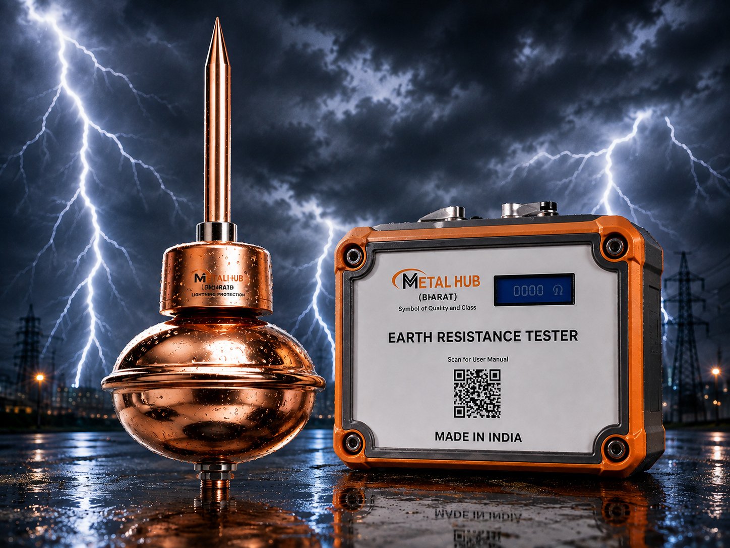
Tested to NFC 17-102 with IP67 digital counters certified at 100kA.
View DetailsShare sizes and quantities — we'll quote the same working day.