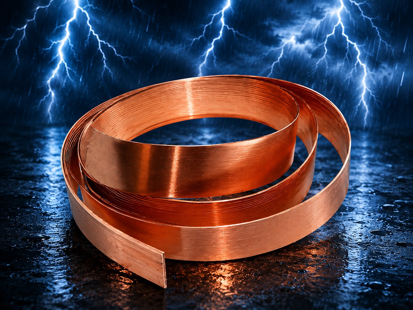
Hot-dip galvanized strips with minimum 86 micron zinc coating — the durable conductor for earthing grids, bonding and down conductors.

Our GI earthing strips are hot-dip galvanized to a minimum zinc coating of 86 microns — well above typical market thickness — giving a typical service life of 15 years or more even in aggressive soil conditions.
Available in sizes from 25×3 mm up to 100×12 mm, they form the backbone of earthing grids, equipment bonding runs and lightning down-conductor networks.
| Material | Mild steel, hot-dip galvanized |
|---|---|
| Zinc Coating | Minimum 86 micron |
| Size Range | 25×3 mm to 100×12 mm |
| Supply | Standard lengths or as per requirement |
| Service Life | 15+ years typical |
Almost every earthing system in the country runs on GI strip somewhere: electrode to panel, panel to panel, column bonding, fence earthing, cable armour bonds. The strip's rectangular section maximises surface area per kilogram — an advantage over round conductor for both fault-current dissipation and impulse (skin-effect) behaviour — while remaining easy to clamp, drill, bend and weld on site.
The failure mode of cheap strip is invisible: under-thickness zinc. Market-grade material is often electro-galvanized to a few microns and looks identical to hot-dip on the shelf, but underground it can begin rusting within two or three monsoons — and a corroded strip breaks the earth path even when the electrodes remain healthy.
Metal Hub strips are hot-dip galvanized to a minimum coating of 86 microns, aligned with IS hot-dip practice, giving a typical service life of 15 years and more in normal soils. Sizes run from 25×3 mm for light bonding to 100×12 mm for substation risers, in standard lengths or coils to order.
Sizing is a genuine engineering decision: the strip must carry the prospective fault current for the protection clearing time without exceeding its temperature limit, with a corrosion allowance for buried runs. The tables below give the working data; our engineers verify project-specific sizing free of charge.
Good to know: For buried runs, specify one size thicker than the bare electrical calculation requires — the extra section is your corrosion allowance for the out-years.
For the same cross-sectional area, a flat strip presents far more surface than a round conductor. Surface is what matters twice over: buried, it is the dissipation interface with soil; under impulse conditions, skin effect pushes current to the conductor surface, so the strip's perimeter sets its effective impulse impedance.
Strip is also the practical choice at joints. Flat-to-flat overlap joints are simple to bolt or weld with full contact area, and clamp accessories for electrodes, structures and cable armour are all designed around standard strip widths.
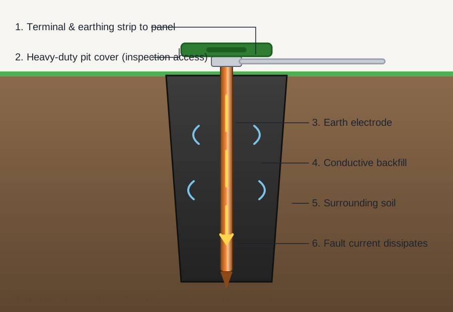
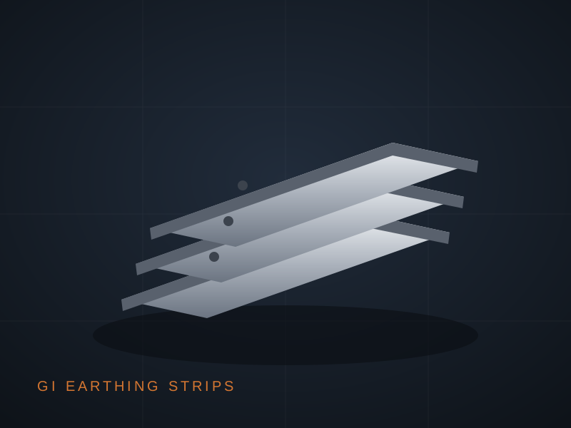
Weight basis: steel at 7.85 g/cm³, excluding zinc. Standard lengths or coils to order.
| Size (mm) | Cross-section (mm²) | Approx. weight (kg/m) | Typical duty |
|---|---|---|---|
| 25 × 3 | 75 | 0.59 | Equipment bonding, light panels |
| 25 × 6 | 150 | 1.18 | Panel earthing, small DGs |
| 32 × 6 | 192 | 1.51 | Commercial risers |
| 50 × 6 | 300 | 2.36 | Main earthing runs, LT systems |
| 50 × 8 | 400 | 3.14 | Industrial mains, HT panels |
| 75 × 10 | 750 | 5.89 | Substation connections |
| 100 × 12 | 1200 | 9.42 | Substation risers and grids |
| Property | Value | Why it matters |
|---|---|---|
| Base material | Mild steel, fully annealed | Bends on site without cracking |
| Galvanizing | Hot-dip, all surfaces and edges | Alloyed sacrificial protection |
| Minimum zinc coating | 86 micron | 15+ year typical buried life |
| Supply forms | Standard lengths / coils | Fewer joints on long runs |
| Standard | Title / scope | Relevance |
|---|---|---|
| IS 3043 | Code of practice for earthing | Conductor sizing and installation practice |
| IS 2309 | Lightning protection of buildings | Down conductor and bonding requirements |
| IEC 62561-2 | LPS components — conductors and electrodes | Cross-section and material requirements |
| IS 4736 / IS 2629 | Hot-dip galvanizing | Zinc coating quality for GI strips |
First-pass guidance for typical clearing times; final sizing per IS 3043 calculation for your fault level.
| Application | Common strip size | Note |
|---|---|---|
| Domestic / small shop earthing | 25 × 3 mm | Pair per electrode |
| Commercial panel earthing | 25 × 6 / 32 × 6 mm | Ring or radial to pits |
| DG set / transformer LT neutral | 50 × 6 mm | Duplicate runs per code |
| Industrial main earth bus | 50 × 8 mm | With corrosion allowance buried |
| HT yard riser / grid tail | 75 × 10 / 100 × 12 mm | Per grid design calculation |
| Parameter | GI strip | Copper strip |
|---|---|---|
| Relative cost | Low | High |
| Conductivity | Good (steel + zinc) | Excellent |
| Buried life | 15+ years (86 µ coating) | 40+ years |
| Theft attractiveness | Low | High |
| Best fit | General LT/commercial runs | HV, lightning, clean-earth paths |
Shortest practical path, avoiding chemically aggressive ground; buried depth typically 500 – 600 mm below finished level.
Uniform depth, stone-free bedding; in rocky or high-resistivity ground, bed the strip in conductive compound.
Lay the strip on its wide face for maximum soil contact and mechanical stability.
Overlap at least 50 mm and secure with two GI bolts or continuous weld; paint welded joints with zinc-rich primer plus bitumen.
Take risers up walls or structures on saddles, protecting against mechanical damage at floor level.
Backfill without stones against the strip, reinstate, and record the route on the earthing layout drawing.
A buried strip cannot be inspected along its length, so system health is proven at its ends: continuity checks between pits and panels, and the earth-loop values at equipment. Any unexplained rise points to a joint or a damaged section, most often at the soil-air transition where corrosion concentrates.
At risers and test points, the visual telltale is simple: white zinc bloom is the coating doing its sacrificial job; red rust is the signal that the coating is finished at that spot and remediation is due.
Zinc corrodes at a broadly predictable rate in soil, so life scales with thickness. At 86 microns you can plan on 15+ years buried in normal soil; thin electro-galvanized strip may not survive three.
It depends on fault level and clearing time per IS 3043, plus a corrosion allowance if buried. The quick table above orients you; send us your fault level and we return the calculation at no charge.
Overlap 50 mm minimum with two GI bolts, or weld continuously; then restore protection with zinc-rich primer and a bitumen overcoat on buried joints. The joint should never be the weakest link.
Not underground — the galvanic couple strips zinc quickly. Use a bimetallic connector above grade, or run copper strip below grade to a copper electrode.
More surface per kilogram: better soil dissipation, better impulse behaviour, and easier, fuller-contact joints with standard clamps.
Yes — standard lengths, custom cut lengths, and coils for long trench runs that minimise the number of buried joints.
Share sizes and quantities — we'll quote the same working day.